Hitachi 60SBX78B User Manual
Browse online or download User Manual for TVs & monitors Hitachi 60SBX78B. Hitachi 60SBX78B User's Manual
- Page / 99
- Table of contents
- TROUBLESHOOTING
- BOOKMARKS
- SERVICE MANUAL 1
- SAFETY NOTICE 2
- WARNING 2
- SAFETY PRECAUTIONS 3
- Shield Plate A 4
- SERVICING PRECAUTIONS 6
- BARE JUMPER 8
- DEfECTlVE 8
- 1ST DIGIT 9
- MH DIODE RESISTOR 9
- TECHNICAL CAUTIONS 10
- SPECIFICATIONS 11
- Fig. 3. Control Panel 12
- I”““““’ 13
- TV GUIDE PLUS+ 15
- 4 6 6 7 16
- STEP 5 17
- SET UP TV GUIDE Plus+ 17
- STEP 4 17
- STEP 6 18
- Cable TV Box 18
- STEP 7 18
- STEP 8 19
- STEP 9 19
- -“’ i - - : 20
- :$j,i :,I 20
- END OF SET UP 21
- SERVICE ADJUSTMENTS 23
- CROSS-HATCH 26
- 60” 8OOk 29
- 50” 65Ok 29
- (,V 1970k5min 1 30
- [SIGNAL P.W.B ) 36
- 3.3 MAIN CHASSIS 37
- (Power/Deflection P.W.B.) 37
- TROUBLESHOOTING 39
- 2. No Picture 41
- Main Picture 42
- Sub Picture 42
- 5v P-P 43
- (,,“,““Ell 44
- 6. No Sound 45
- DCU REPAIR TABLE 46
- ._ .-_ 47
- EXPLODED MEW 71
- REPLACEMENT PARTS LIST 72
Summary of Contents
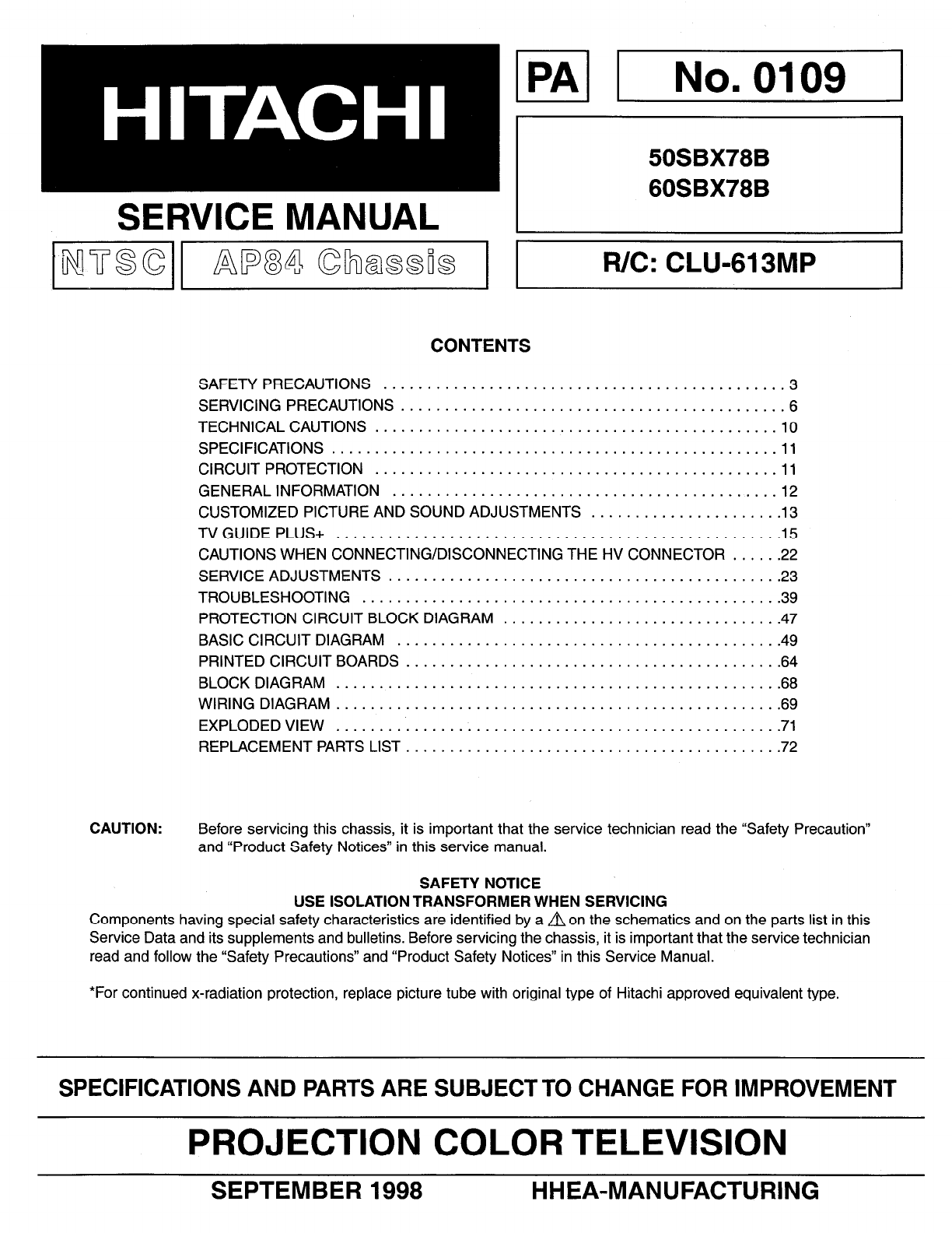
SERVICE MANUAL CONTENTS SAFETY PRECAUTIONS ... .3 SERVICING PRECAUTIONS ...
TECHNICAL CAUTIONS High Voltage limiter circuit operation check. 1. Turn off TV and connect jig as shown in Figure 2. Adjust jig fu
SPECIFICATIONS Model: 50SBX78B 6OSBX78B Cathode-Ray Tube: R=Pi GLFTOORFA G=PlGLFTOOHLA B=Pi GLFTOOBMB Power Input: 120 volts AC, 60 Hz Power Con
GENERAL INFORMATION TV/Video Source Selector TV/Video Source Selector a&c Focus Rear Speaker Terminals-, Fig. 3. Control Panel _ S-Vide
CUSTOMIZED PICTURE AND SOUND ADJUSTMENTS Select VIDEO to adjust picture settings and improve picture quality. CURSOR CONTRAST 4-I, 75%
Select AUDIO SETTINGS to adjust the TV to your preference and to improve the sound quality. BASS 4”,72% TREBLE 4-I) 50% BALANCE 4---I
jSetUD1 TV GUIDE PLUS+ This feature allows you to view program information for up to 1 week in the future. It also allows you to
SET UP TV GUIDE Plus+ Before you can use TV GUIDE Plus+ you must perform the setup. Simply use your illuminated remote control to
SET UP TV GUIDE Plus+ STEP 4 1. Use the CURSOR button to select YES or NO, then press SELECT. 2. If you select YES, you will go
SET UP TV GUIDE Plus+ STEP 6 1. Turn your cable box ON and tune it to channel 02. 2. Use the CURSOR buttons to select your cabl
SET UP TV GUIDE Plus+ STEP 8 1. Using the CURSOR buttons, select the channel number to which your cable box Output is set. It is
SAFETY NOTICE USE ISOLATION TRANSFORMER WHEN SERVICING Components having special safety characteristics are identified by anon the sche
SET UP TV GUIDE Plus+ -“’ i - - : 0 LA!9 :$j,i :,I ; , : Set U STEP 10 1. Tune your VCR to channel 02, then turn if OFF. 2. Use the
END OF SET UP 1. A screen telling you that TV GUIDE Plus+ will be ready for use within 24 hours appears. Make sure that you tu
CAUTIONS WHEN CONNECTING / DISCONNECTING THE HV CONNECTOR Perform the following when the HV connector (anode connector) is removed or
SERVICE ADJUSTMENTS 1. ASSEMBLED P.W.B. ADJUSTMENT ... .24 l-l. Memory Initialization ...
* 1. ASSEMBLED P.W.B. ADJUSTMENT 1 .l Memory Initialization Adjustment procedure (1) Press INPUT key on Control Panel and then Power On
2. FINAL ASSEMBLY ADJUSTMENT 2.1 Focus adjustment Adiustment preparation (1) (2) (3) (4) The set can face in any direction: west, east,
Notes: (1) Fixing screw (2) Color aberration FIXING SCREW COLOR ABERRATION CROSS-HATCH (3) Since the G light is very important for pi
2.4 Sub picture white balance adjustment (ROM4, ROM6, ROM6) Adjustment preparation (1) Start adjustment after power is ON for 20 minut
2.5.4 Matrix surround/monaural check Adjustment procedure l Check that the following waveforms are obtained. (Input signal @ only) l Fron
(4) (5) Turn the deflection yoke of R or B and set so that the inclination of R or B with respect to the green light is as show
SAFETY PRECAUTIONS Before returning an instrument to the customer, always make a safety check of the entire instrument, including but
2.9 Horizontal size adjustment (R603) Adjustment preparation (1) I;; (4) (5) (6) (7) The set’can face east or west. Input the single cros
PRT SURFACE SIDE 1 e 4-POLE BEAM SHAPE CORRECTION MAGNET 2-POLE BEAM ALIGNMENT TRUE CIRCLE SPECIFICATION MAGNET TRUE CIRCLE DEGREE: a/b SPE
(5) (6) Press the service only switch (on POWER/DEFLECTION PWB). The pattern displayed is now the digital convergence mode. When performi
2.14.3 Convergence point adjustment Adjustment preparation (1) Select color to adjust. “RECALL’ - Green “0” - Red “INPUT” - Blue (2) Us
2.15 GUIDE+ OSD Adjustment Adjustment preparation (1) Receive any signal in ANT A. (2) Set picture controls to shipping conditions. (3)
3. ADJUSTMENT POINT 3.1 CRT, cabinet locations FRONT OF TV P P P 1. CENTERING MAGNET FOR RED PRT 2.CENTERING MAGNET FOR GREEN PRT 3.CENT
3.2 MAIN CHASSIS (Signal P.W.B.) 240 I ISCII ISC2[ O- \. J 888 ROM8 ROM6 ROM4 (Blue) (Green) (Red) 1 0 1102 0 c El 1001 [SIGNAL P.W.B ) SURROU
3.3 MAIN CHASSIS (Power/Deflection P.W.B.) 325- @ Bz lz %85 I ixl 0977 AUDIO 22v SKOI: SERVICE ONLY button (CONV. ADJ) I I D965 +G 9V q D946 l
3.4 CPT (R) (G) (B), Focus Pack, Control P.W.B. GND \ BLUE 0 0 I FJ GND GREEN DRIVE GND RED DRIVE GREEN RED 0 0 0 c A FOCUS PACK (UFPK
TROUBLESHOOTING 1. No Raster and No Power (REPAIR METHOD) Red LED “ON”? No I Yes PROTECT line Connector PYI , D964 (Al 2V) Check A12V line
X-radiation - TUBE: The primary source of X- radiation in this receiver is the picture tube. The tube utilized for the above mentio
Voltage at pin (5) of No.““~..“.:::“. Yes E991 blown Yes Check 1901, D911, D910, D969 Replace E991 Does raster Yes v Check 1905, 1903, 19
2. No Picture Normal Abnormal 0517, Q516, Q515 Does on-screen No v 1501, 1903, 1001, I1 02, 1006 Q108, Q109, QllO, Q008 Yes Normal Abnorm
3. Reception Impossible with Snow Noise Main Picture I No Yes Yes Sub Picture eception impossible with snow noise No Yes Yes u102 Yes Vcc
4. Defective Synchronization llefective synchronization 1 cl902 I I ivormal I 1- 1r T 5v P-P .I 43
5. Incorrect Color \ When normal c lncorreitcolor ) Color condition No color Defective white balance Yes No (,,“,““Ell L 1501, X501, etc. Ye
6. No Sound OV or lower 26V E997 +26V Power Supply L I Yes I Check the I ‘C bus (SCL, SDA) Yes No l Check IS12 Yes No IYOl (1) Check the
7. Convergence Errors. If an error message or code appears while performing MAGIC FOCUS or Initialize (MOVE, PIP CH in service mode
1 AC Input v Fuse F901 Switching Transformer T901 E997 Rectifier +26 : 0913 +32V I E998 7000 I Audio E993 D977 ) +22v Rectifier 4000 +22v - +22 :
2. 3. 4. 5. 6. Read and comply with all caution and safety-related notes on or inside the receiver cabinet, on the receiver chassis,
SERVICING PRECAUTIONS CAUTION: Before servicing instruments covered by this service data and its supplements and addenda, read and foll
General Soldering Guidelines 1. Use a grounded-tip, low-wattage soldering iron and appropriate tip size and shape that will maintain
EXPLODED MEW NOTES: Some parts may appear different than those shown in the Exploded View. When ordering, refer to the Replacement
REPLACEMENT PARTS LIST PRODUCT SERVICE NOTE: Components marked w ith a ‘A ! have special characteristics important to safety. Before
REPLACEMENT PARTS LIST PRODUCT SERVICE NOTE: Components marked w ith a A ! have special characteristics important to safety. Before r
REPLACEMENT PARTS LIST PRODUCT SERVICE NOTE: Components marked w ith a n ! have special characteristics important to safety. Before re
REPLACEMENT PARTS LIST PRODUCT SERVICE NOTE: Components marked w ith a n ! have special characteristics important to safety. Before r
REPLACEMENT PARTS LIST PRODUCT SERVICE NOTE: Components marked w ith a n ! have special characteristics important to safety. Before re
REPLACEMENT PARTS LIST PRODUCT SERVICE NOTE: Components marked with a n ! have special characteristics important to safety. Before rep
REPLACEMENT PARTS LIST PRODUCT SERVICE NOTE: Components marked w ith a n ! have special characteristics important to safety. Before r
REPLACEMENT PARTS LIST PRODUCT SERVICE NOTE: Components marked with a A ! have special characteristics important to safety. Before rep
Fuses and Conventional Resistor Removal/Replacement 1. Clip each fuse or resistor lead at top of circuit board hollow stake. 2. Secur
REPLACEMENT PARTS LIST PRODUCT SERVICE NOTE: Components marked with a A ! have special characteristics important to safety. Before r
REPLACEMENT PARTS LIST PRODUCT SERVICE NOTE: Components marked with a A ! have special characteristics important to safety. Before re
REPLACEMENT PARTS LIST PRODUCT SERVICE NOTE: Components marked with a n ! have special characteristics important to safety. Before re
REPLACEMENT PARTS LIST PRODUCT SERVICE NOTE: Components marked with a n ! have special characteristics important to safety. Before rep
REPLACEMENT PARTS LIST PRODUCT SERVICE NOTE: Components marked with a n ! have special characteristics important to safety. Before rep
REPLACEMENT PARTS LIST PRODUCT SERVICE NOTE: Components marked with a n ! have special characteristics important to safety. Before rep
REPLACEMENT PARTS LIST PRODUCT SERVICE NOTE: Components marked w ith a n ! have special characteristics important to safety. Before re
REPLACEMENT PARTS LIST PRODUCT SERVICE NOTE: Components marked with a A ! have special characteristics important to safety. Before r
REPLACEMENT PARTS LIST PRODUCT SERVICE NOTE: Components marked with a n ! have special characteristics important to safety. Before repl
REPLACEMENT PARTS LIST PRODUCT SERVICE NOTE: Components marked with a a ! have special characteristics important to safety. Before repl
NOTE: These components are affixed with glue. Be careful not to break or damage any foil under the component or at the pins of
REPLACEMENT PARTS LIST PRODUCT SERVICE NOTE: Components marked with a n ! have special characteristics important to safety. Before r
REPLACEMENT PARTS LIST PRODUCT SERVICE NOTE: Components marked with a n ! have special characteristics important to safety. Before r
REPLACEMENT PARTS LIST PRODUCT SERVICE NOTE: Components marked with a n ! have special characteristics important to safety. Before re
REPLACEMENT PARTS LIST PRODUCT SERVICE NOTE: Components marked with a A ! have special characteristics important to safety. Before re
REPLACEMENT PARTS LIST PRODUCT SERVICE NOTE: Components marked with a n ! have special characteristics important to safety. Before rep
REPLACEMENT PARTS LIST PRODUCT SERVICE NOTE: Components marked with a A ! have special characteristics important to safety. Before repl
REPLACEMENT PARTS LIST PRODUCT SERVICE NOTE: Components marked with a A ! have special characteristics important to safety. Before repl
REPLACEMENT PARTS LIST PRODUCT SERVICE NOTE: Components marked with a n ! have special characteristics important to safety. Before r
REPLACEMENT PARTS LIST PRODUCT SERVICE NOTE: Components marked with a n ! have special characteristics important to safety. Before rep
NOTES:
Related products and manuals for TVs & monitors Hitachi 60SBX78B


 (142 pages)
© 2020, manymanuals.com. All rights reserved. | 0.627 s |
 Manymanuals.com
 Manymanuals.de
 Manymanuals.fr
 Manymanuals.it
 Manymanuals.pl
 Manymanuals.cz
 Manymanuals.es
 Manymanuals-pt.com
Comments to this Manuals